Creating Programs
Print programs can be created and edited in the Program Editor. Start Program Editor by clicking on the "E" shortcut on the computer desktop.Before creating a new program you need the following information. 1. How many samples have to be printed. 2. What type of the source plate will be used. 3. What spot pattern will be printed on the array. 4. How many substrates will be printed. All other information, such as location of the samples in the microplate wells or samples annotation can be added after the print program is created and tested.
Example Program #1
This program will have the following features: 1. Number of samples to pe printed: 4 (named A, B, C, D ) Samples will be placed in 4 corner wells of a 96 well microplate. 2. Pickup will be made form a 96 well plate ( with round wells ). 3. Microarray spotting: each sample will be printed in 4 repetitions in 2x2 layout A A A A Distance between spots = 1mm Groups of repetitions will be arranged in 2x2 layout A A B B A A B B C C D D C C D D With 1mm distance between the groups. 4. The array will be printed on 3 substrates size of a microscope glass ( 75mm x 25mm ). The program will consist of 5 steps. 1. Pickup ( picking up samples from source plate ) 2. Prespot ( making 4 hits on a separate substrate to leave excess liquid ). 3. Print ( printing microarrays on 3 substrates ). 4. Wash ( visit washing station ). 5. Dry ( visit vacuum drying station ). For each step must be created a pattern consists of the point the arrayer should visit during this step.Creating Pickup Pattern
Pickup Pattern will contain points the arrayer will be visiting during program execution to pickup 4 samples. The pickup pattern can be created from a template available with the microarryer ( since it should be created for a standard labware ).Open a template pattern
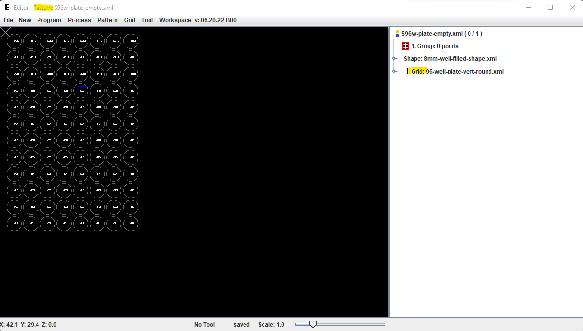
Template patterns names start with the "$" symbol. Use Pattern > Open menu item and select "$96w-plate-empty.xml" file.It contains an empty patterns with a Grid representing wells of the 96 well plate. NOTE: The template patterns are no different from created by users. They are supplied with the system and created for a standard labware or operations typically used in any program ( such as Washing and Drying patterns ).
Rename the template pattern
Use File > Save As menu item and choose a new name for the pattern. ( "demo-pickup-pat" for this example )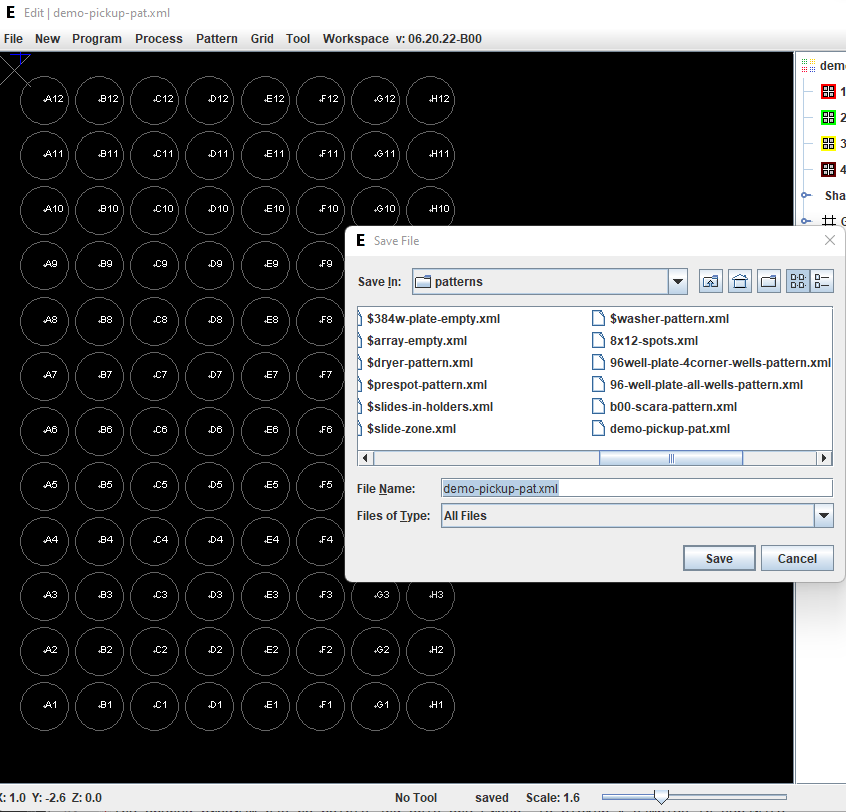
Create groups
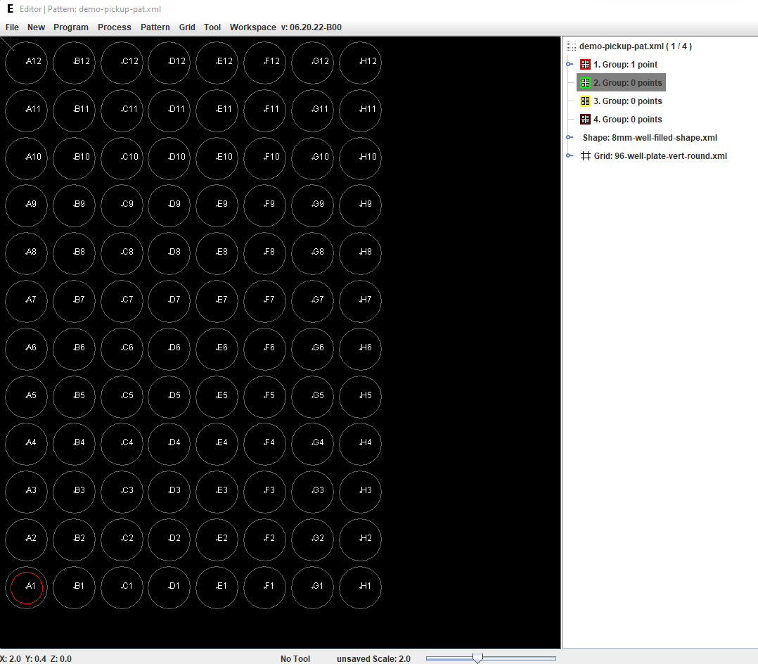
The opened pattern has no points and only one Group. To pickup 4 samples in separate program cycles it is necessary to create 4 Groups and add a point to each of them. NOTE: Points define location of the samples. Groups define sequence of visiting points. Right-click with the mouse on the Pattern Name line ( demo-pickup-pat.xml ) in the tree view and select "Add Group" menu item.Repeat the same action four times to create four Groups.
The groups will be used to place four points ( one points in each group ). The groups are marked with a color. Points assigned to the groups will be marked with same color in the Work Board View. Points in the patterns in other program steps will also be colored with the same color in the corresponding groups. Points with the same color across all steps will be visited during the same program cycle: Pickup->Prespot->Print->Wash->Dry
Using the grid
The opened pattern has a Grid attached to it. The name of the grid "96-well-plate-vert-round" means that every Node of the grid corresponds to a well in a standard 96 well plate ( 8x12 wells, 9mm distance ). The plate is positioned vertically on the screen and the well are round. NOTE:This grid and other typical grids are supplied with the system. Custom grids can be created and saved under the Grid menu item. The grid nodes are shown as gray circles and marked with the microplate well number.If you click with the mouse near a node the cursor ( blue cross ) will snap to the center of the nearest node.
Create patten points
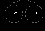
The points are created by mouse Double-click ( left button) near a node ( well ) on the grid. IMPORTANT! Before creating a point select a Group in the tree view where you want to assign the point. If no groups are selected in the Tree View, no points will be created.Double-click near "A1" grid node. The point will appear in this node.
Initially the point will look like a white filled circle. This is because the group is selected ( in the Tree View on the right ).
NOTE: If you select a group in the Tree View, all points belong to this group will be highlighted with white filled circle. If you select an individual point, only this point will be highlighted in the Work Board View. When you select another group, the newly created point will be shown as a red circle, the same color as the group it belongs to.
Deleting a point
Points can be deleted by Double-clicking with the RIGHT button of the mouse near the point. NOTE: You need to select a group in the Tree View from which you want to delete a point. If no group is selected, no point will be deleted. A point can also be deleted in the Tree View. Expand the Group Tree Node > Select Point Leaf > Left-click > Delete menu item.Create 4 points in the 4 corner wells of the microplate. ( Consecutively selecting the groups ). In result there should be one point in each group. Four points in the Work Board View will be shown in different colors.
Save the patten by selecting File > Menu item.
Creating Microarray Spotting Pattern
Microarray spotting: each sample will be printed in 4 repetitions in 2x2 layout Distance between spots = 1mm. Groups of repetitions will be arranged in 2x2 layout A A B B A A B B C C D D C C D D There is no template pattern for this microarray pattern. It has to be created from scratch.Create New Pattern
Use New > Pattern menu item to create a new pattern.A new pattern comes with one Group, no points, no shape and no grid.
Add Shape to the Pattern
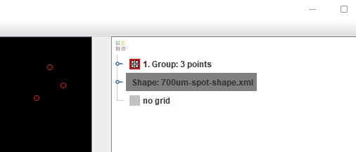
Shape defines the way points in the pattern are drawn on the screen. Typically point shapes correspond to the size of the pins used to print this particular array. The software comes with many predefined shape files to choose from. However custom shapes can be created and saved by users. NOTE: If no shape is chosen for the pattern all points are drawn as small blue crosses. They will remain Blue regarding of the group color.To choose a Shape Right-click with mouse on the Pattern Icon in the tree view and select Choose Shape menu item.
From the opened File Select dialog choose "700um-spot-shape.xml" and click [Open] button. The Shape will appear in the Tree View in the Shape leaf. After the shape is chosen, the points will start looking like 0.7mm circles. The points will also change color corresponding to the color of the Group they belong to.
Add Grid to the Pattern
Without a Grid points in the pattern can be placed at arbitrary coordinates. However it is difficult to place them in a regular order. Applying a regular grid will allow cursor to snap to the grid nodes. Since the created print pattern should have 1mm distance between the points, the we need to create a grid with 1mm distance between the nodes. Open Pattern > Apply Grid menu item.In the Grid Dialog set the grid parameters Grid size = 10mm, Grid step = 1mm in both X and Y directions.
This way you will create a grid of 100 nodes in 10x10 format. Increase the Scale to magnify the Grid.
NOTE:The Grid leaf in the Tree View shows "no file". It means that the grid will not be saved when you save the pattern. If you need a Grid that can be attached to a pattern permanently you need to create a grid ( menu New > Grid ) and save it in a file. Then select the grid file to attach it to the pattern.
Add Groups and Points to the Pattern
Since we need to accommodate 4 samples ( 4 repetitions each ) on the array we need to create 4 Groups and 16 points. Each group will contain 4 points. Right-click on the Pattern Icon in the Tree View and select Add Group menu item. Create 4 groups in the pattern.Select Group #1 in the Tree View. Double-click ( left mouse button ) near 4 nodes on the grid in the upper-left corner to create 4 points.
Select next group and repeat the operation until you create 16 points ( 4 points for each group ). NOTE: If you need to delete a point, select a group and Double-click with the Right mouse button.
Save the pattern ( File > Save menu item ).
Create Prespot Pattern
Prespotting ( a few hits on a separate substrate to remove excessive liquid from the pin after the pickup ) will require 4 hits after sample pickup. Since the first couple of spots may be bigger than regular ( due to excessive liquid on the pin ) it is necessary to place areas with different sample further away from each other. Distance between spot groups should be 2mm. AA BB AA BB CC DD CC DD This pattern can be created the same way the previous Spot patterns was created. - Create new pattern ( New > Pattern menu ) - Save the new pattern with "demo-prespot-pat.xml" name - Choose "700um-spot-shape" for the pattern - Apply (Pattern > Apply Grid) 10x10 Grid to the pattern with 1mm distance between grid nodes. - Add 4 Groups to the pattern. - Create 16 spots ( 4 for each group ) The Prespot pattern should look like this: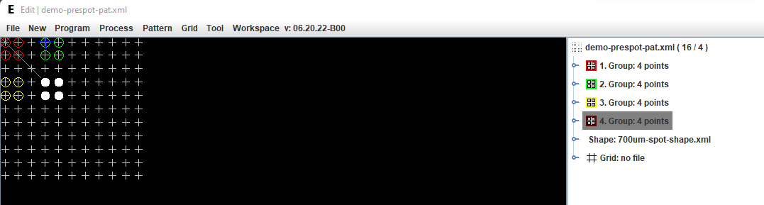
Wash and Dry Patterns
Wash and Dry patterns are the same for all programs. They are provided with the software. Both patterns consist of a single point with 0, 0, 0 coordinates.Create Program Steps
Click Program > New menu item. The new , empty program will be created.Save New Program
Click File > Save As and save the program with a new name "demo-program.xml".The program currently has no steps. To add a step In the Tree View click on the Program > Add Step menu item.
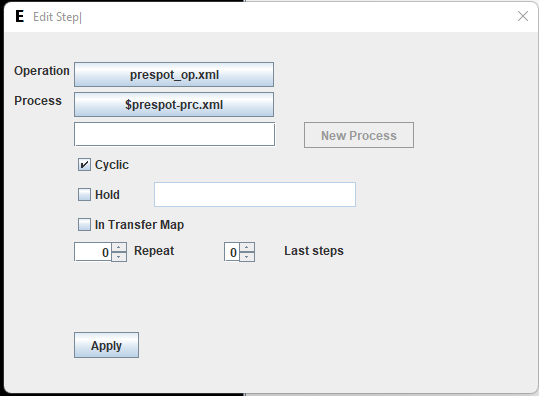
It will open the Edit Step dialog window.
Click on [Select Operation] button and choose "pickup-op.xlm" from the file chooser menu.
Click on [Select Process] button and choose "$96w-pickup-prc.xml" from the file chooser menu.
Click [Apply] button.
Replace Pickup Pattern
The selected step is one of standard steps supplied with the software. It contains and empty pickup pattern. This pattern can be edited to add points, but since we have already created the demo pickup pattern, we can simple replace the empty pattern with the one that has been created earlier. - Expand the Pattern Node in the Tree View and the Process node. - Right-Click on the Pattern node ($96w-plate-empty) and select Remove menu item.- Confirm removal of the pattern. - Insert the new pattern. Right-click on the Pattern Layers leaf and select Add Pattern menu item.
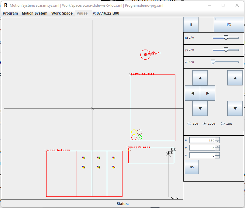
- In the opened File Chooser dialog select "demo-pickup-pat.xml" file that was created earlier. The tree view will show the demo-pickup-pat.xml in the Pattern leaf. And in the Work Board view the pattern points will appear in the Plate Holders location.
NOTE All patterns are placed between "Start" and "Origin". (Which are also special patterns ). Start defines position from which the Operation ( spot operation in this case starts ). Origin defines position of the corresponding Work Board Location ( Plate holder in this case .)
Create other Program Steps
Create remaining program steps repeating actions described above for the Pickup step. - Prespot - Spot - Wash - Dry Use pre-created Operations and Processes for the steps.Prespot Step
Spot Step
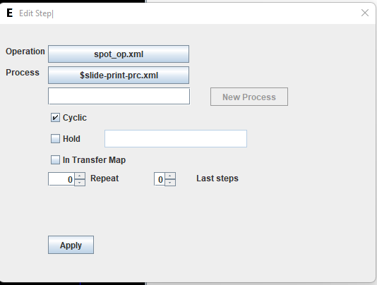
Wash Step
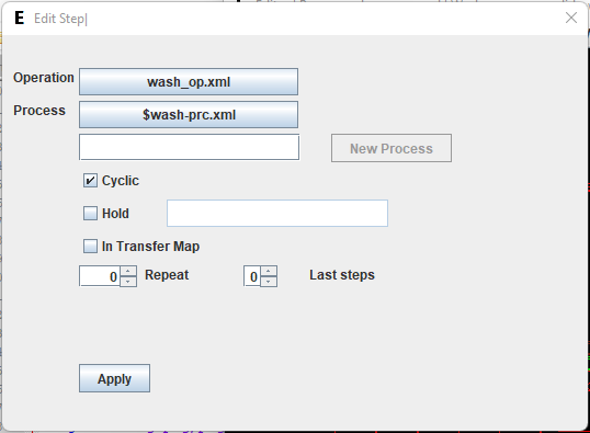
Dry Step
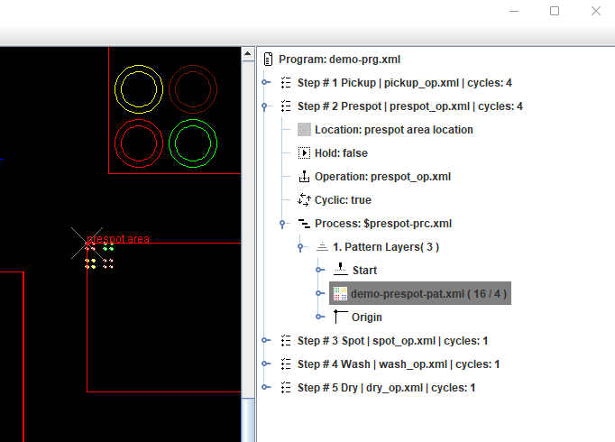
Finally the Tree View should look in the following way:

Replace Empty Patterns in Prespot Step
Prespot and Spot steps contain empty patterns ( as placeholders ). They have to be replaced by the "demo-prespot" and "demo-spot" patterns created earlier. ( The same way it was done for the Pickup step ).In the Tree View: - Expand "Step #2 Prespot " node - Expand "Process $prespot-prc" node - Right-click on the Pattern leaf ("$prespot-pattern.xml") and choose Remove menu item. - Confirm removal [Yes] button. - Right-Click on the "Pattern Layers" leaf. Choose "Add Pattern" menu item. - In the opened File Chooser dialog select "demo-prespot-pat.xml" and click [Open] button. The "demo-prespot-pat.xml" will appear in the tree and the points corresponding to this pattern will show up in the "Prespot Area" location in the Work Board view.
Replace Empty Pattern in Spot Step
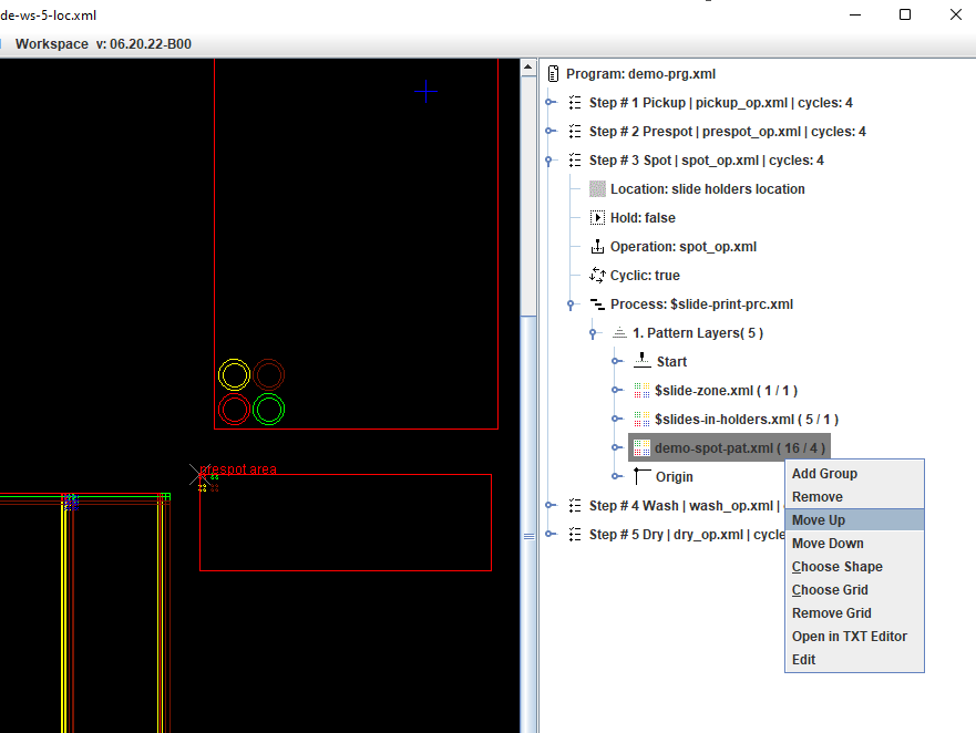
In the Tree View: - Expand "Step #3 Spot " node - Expand "Process $slide-print-prc" node - Right-click on the upper Pattern leaf ("$array-empty.xml") and choose Remove menu item. - Confirm removal [Yes] button.- Right-Click on the "Pattern Layers" leaf. Choose "Add Pattern" menu item. - In the opened File Chooser dialog select "demo-spot-pat.xml" and click [Open] button. NOTE:The "demo-spot-pat.xml" will appear at the BOTTOM of the pattern layers. It has to be moved up on the very top of the Pattern Layers.
Move Spot Pattern Up
- Right-Click on the Pattern leaf ( demo-spot-pat.xml ) - Select "Move Up" menu item. (The pattern will move one layer up) - Repeat this step one more time. The "demo-spot.xml" should appear on the top of the Pattern Layer list.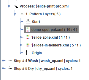
Reposition Spot Pattern on the Slide Substrates
The Spot Step process contains three pattern layers. Expand the Pattern Node and the Process node to see them in the Tree View.The first layer "$array-empty" contains the microarray points. The second layer "$slide-zone" is responsible for defining array Zones on the substrate. Currently it has one spot with x=1.0, y=1.0, z=0.0 coordinates. All microarray points ( in the upper pattern ) are placed relative to the points of the "$slide-zone" pattern. Currently points of array are located in the upper left corner of the slides because the "$slide-zone" zone point has coordinates with x=1.0, y=1.0 ( 1 mm from upper-left corner of the slide) NOTE:The $slide-zone pattern has no Shape attached to it. So all its points are indicated with a Blue cross "X"
If you need to reposition the microarray to the center of the slides you just need to edit the coordinated of the point in the "$slide-zone" pattern. - Expand the "$slide-zone" Pattern node in the tree view - Expand the 1 Group node in the tree view - Right-Click on the Point leaf - Select "Edit" menu item.
In the opened Point Edit dialog enter new coordinates to place the point approximately in the middle of the slide x = 10, y = 25
After that all microarrays will reposition to the slide center.
Adding Arrays on Slide
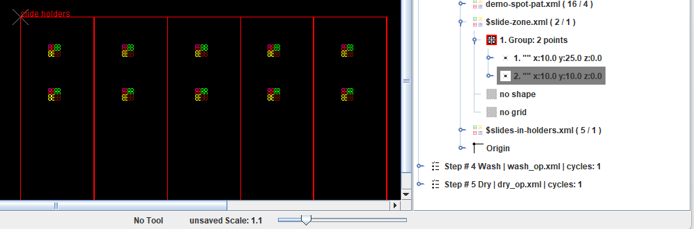
The array can be repeated in multiple locations on the same slide. To multiply the array add more points to the "$slide-zone" pattern. - Expand the "$slide-zone" Pattern node in the tree view - Right-Click on the 1. Group leaf - Select "Add Point" menu item.This will create a new point with 0,0,0 coordinates in the 1. Group.
Edit the coordinates of the newly created points: x = 10; y = 10; This will add a new microarry zone on the slide. Each slide will contain two identical microarrays.
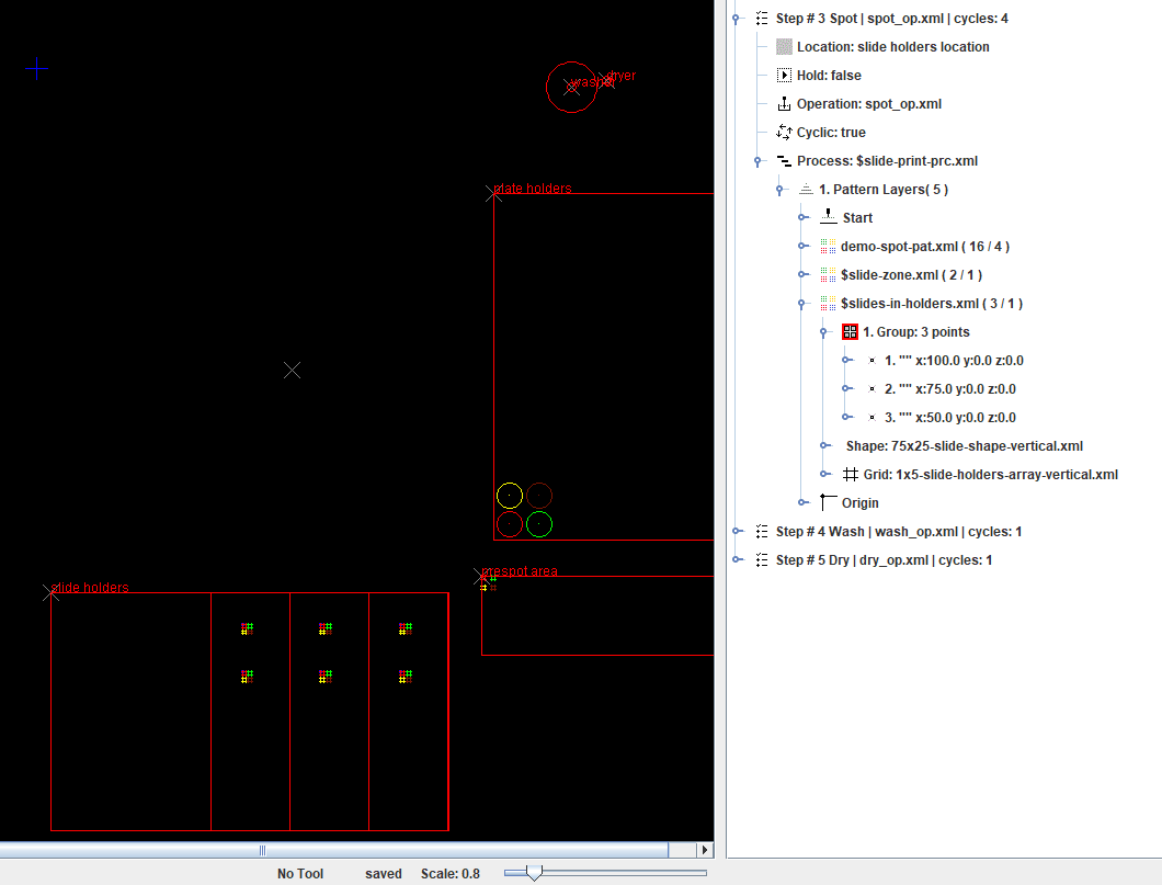
Define Substrates Positions
Substrates positions for printing are defined in the third level pattern "$slides-in-holders". The pattern by default contains 5 points - for all slide holders available on the arrayer Work Board. The slides are highlighted when the corresponding points in the Tree View are selected.According to the program specification only 3 holders should be used. In order to remove 2 slides from the program remove 2 points from the "$slides-in-holders.xml" pattern. - Expand "$slides-in-holders.xml" leaf in the Tree View - Right-Click on the 5th point leaf. - Select "Delete" menu item.
The point will be deleted and the corresponding slide will be removed form the Work Board View. Repeat the same actions with the next 4. point in the "$slides-in-holders.xml" pattern. After deletion of the second point, three points will remain in the "$slides-in-holders.xml" pattern. Three slides will be shown in the Work Board View.
Setting Number of Wash-Dry Cycles
Right-click Dry Cycle in the program Tree View. Select Edit menu item.In the Step Edit dialog set spinners - Repeat - Last Steps
- Repeat defines number of steps repetition. - Last Steps defines how many steps back ( starting from the current step ) will be repeated. If the current step is Dry ( previous step is Wash ) Setting - Repeat: 1 - Last Steps: 2 Will result in one time repetition of last two steps ( Wash and Dry ). ( One repetition means step is executed second time ) - Repeat: 0 will result in a single execution of all steps ( regardless of a Last Steps Settings) NOTE: Currently we know of the only practical use of this setting - for repeating Wash and Dry cycle multiple times as described above. But potentially every step in the program can be set for repetition. ( and Last Steps: can be set for any other step). This may result in intricate patterns of repetitions of the program steps.
Save and Run the Program
Save the program File > Save menu item. The program is ready. It can be opened and run in the Robot Control module.