Microarray Geometry and Features
The Robot Control and Program Editor software modules use certain terminology and naming conventions for modeling microarray geometry and process parameters.Points - Groups - Patterns
Points
During program execution the microarrayer visits certain points on the Work Board. Points represent microarray spots printed on the slide substrates, microplate wells where samples are picked up, washer and dryer chambers and other geometrically defined positions on the work board. Each point is defined by three Coordinates x, y, z. Points also have attributes such as Name and Description. NOTE: All coordinates in the system are in Millimeters Essentially a microarray printing Program is a set of points the arrayer has to visit to pickup samples, transfer them onto substrates and form microarrays.Points Visualization, Shapes
In the software points are shown in the Work Board View and in the Tree View. In the Work Board views the points are visualized with Shapes. Shapes are typically circles or rectangles of appropriate sizes to reflect the corresponding labware element or the microarray features. ( Such as "200um spot" or "7mm round well") In the Tree View Points are shown as Leafs with there coordinates. Points of a 96-well plate. Work Board view on the left ( Shape: circle 8mm ) Tree View on the right.NOTE:Colored circles belongs to points in the Pattern ( filled wells ), Gray circles - points of the plate Grid ( empty wells ) Points with coordinates of five slides. ( Shape: rectangle 25mm x 75mm )
Points with coordinates 16 microarray spots. ( Shape: circle 0.7mm )
Shapes properties are user defined and can be stored in files. The Shapes can be defined in a text mode ( such as "rectangle", size 1mm x 2mm ) or in graphical mode in the form of .bmp image. The shape is drawn at the Coordinates defined by a Point.
Groups and Patterns
The points are combined in Groups and Groups are combined in Patterns. A groups can contain from 0 to unlimited number of Points. A Pattern must contain at least one Group, and up to unlimited number of groups. Groups and Patterns is one way of defining the sequence the arrayer visits the Points during the program execution. ( another ways of defining the sequence are program Steps ). A Shape is attributed to the entire pattern. Which makes every point in the pattern to use the same shape. Each point in a Group are colored with the same color. Every group has its own unique color. Pattern with 4 groups, 4 points in each group ( Group 2 selected in Tree View, all points highlighted )If no Shape is associated with a pattern, all points in this pattern are shown as Blue colored crosses.
NOTE: Shapes and group colors serve only for the program visualization purpose. They do not affect program execution in any way.
Pattern Multiplication
The whole concept of microarray fabrication is repeating the same pattern across multiple locations. This process is called "Pattern multiplication". Examples are: - sample repeated on many zones on the microarray slide - entire microarray repeated on a number of slides In the Program design software Pattern multiplication is done by combining patterns in Stacks. Each pattern in a stack is called a Layer. When two patterns "A" and "B" are combined in a Stack, points of the first pattern are repeated around points of the second pattern. Therefore total number of points in the resulting pattern equals (points A) X (points in B). Pattern A is called "Upper" relative to B. Pattern B is called "Lower" relative to A. Pattern AxB is called "Multiplication" of A and B.In the Program Editor pattern Stacks are part of the Process. Process with AxB pattern Stack.
It can be more than two pattern Layers in a Stack. Every multiplication of Upper patterns is multiplied around points of a Lower pattern. AxBxC pattern
Process with AxB pattern Stack.
In a microarray print program a Process is included in every Program Step. Pattern Stack are used to place arrays on multiple slides and print identical arrays on multiple zones on a slide. In the example below program step called "Spot" contains a Process "Slide Print Prc" The process has three Pattern Layers 1. demo-spot-pat ( contains 16 points - 4 repetitions of each sample ) 2. slide-zone ( contains 2 points - makes 16 spots repeated twice on each slide ) 3. slide-in-holders ( contains 3 points - makes combination of the above patterns repeated on 3 slides )
NOTE: Multiplication of patterns AxB in NOT equal to BxA !
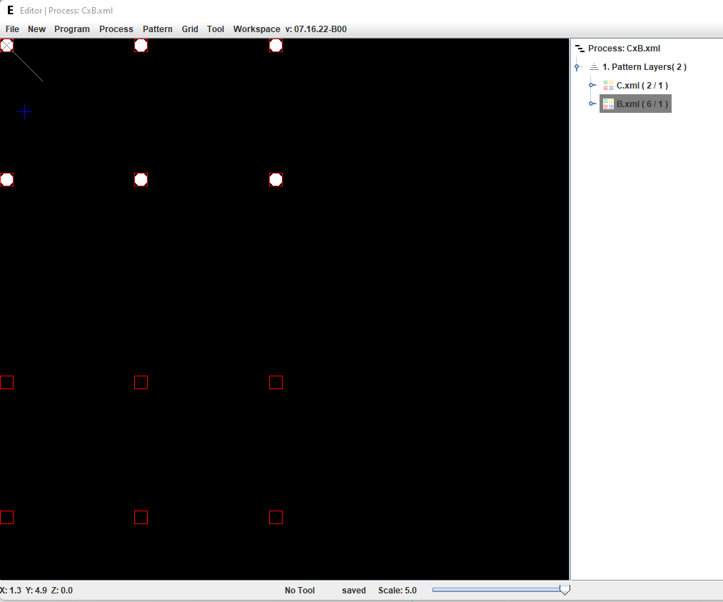
In the Program Editor BxC vs. CxB Multiplication BxC ( B - round points, C - square points )
Multiplication CxB ( B - round points, C - square points )