Robot Control Module
Robot Control software is installed on the computer attached to the microarrayer. It can also be installed on any other computer (Windows, Mac or Linux ) When the arrayer is not powered or when the Robot Control module runs on an computer not connected to the arrayer the software runs in the simulation mode. Almost all GUI controls perform in the same way as on the powered on system except for the actual motion system transitions. In the simulation mode the software can open and perform simulated run of the programs. Some GUI elements - buttons or menu items are disabled (grayed-out) when the software runs in the simulation mode.Launching Robot Control
Click on the "R" shortcut on the computer desktop to launch the Robot Control.Robot control can be also launched from the computer folder. On the Robot computer ( Raspberry PI ) from: home/pi/lnt/r.jar On a Windows PC from: c:/lnt/r.jar When launched the software will display the GUI controls window.
Powering up the system
Click on the "I/O" button in the upper-right corner of the Axes Control panel. When the system is powered the green dot will appear in the corner of the button. The system may perform a few movements during the power-up process. NOTE: It is recommended powering down the system when it is not in use.Manual Controls
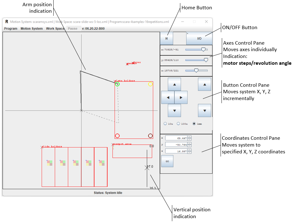
The system can be moved to a desired position by using manual controls. Manual movements are typically required for system calibration.Mouse and Coordinate Controls
The system can be moved by clicking mouse left button anywhere within the work area or entering coordinates into the Coordinates Input Fields. NOTE: With the mouse input the system can be moved only across the horizontal X-Y plane. Vertical transitions require entering a coordinate value into the "z" field.Mouse Input
The new selected position of the robotic arm will be shown by a gray thin line. The dotted line shows an alternative arm configuration for reaching the same position. The system automatically selects an optimal configuration of of the two possible variants. Current position of the arm is shown by the bold black line will not change until the "GO" button is clicked. The Coordinates Input Fields on the right will show the selected position coordinates. NOTE: If a selected position is outside of the arm reach it will be shown by a dotted line ( for both arm configurations ). The "GO" button will be disabled ( and grayed out ) if the selected position is out of reach.
Coordinates Input
When a new coordinate value is entered into a Coordinate field a corresponding arm position is shown on the left. "Z" ( vertical ) position is shown on the right-bottom corner of the work area. The arm will not move until the "GO" button is clicked. NOTE: For the SCARA motion system X-Y zero position is in the center of the work area. The HOME position is different form the zero position. The system is calibrated the way that the HOME position is reached when the arms of the motion system are stretched in a straight line. The HOME position is typically Y=0 X=( Upper arm + Forearm length ).
Incremental Input
The system moves in predefined increments ( 10um, 100um, 1mm ) when one of the arrow buttons is pressed on the Button Controls Panel. The increment values are set with the radio buttons below the Arrow buttons. Clicking on an Arrow button button will result immediate transition of the system to the increment value. Incremental transition is typically is used during system calibration tasks for locating reference points on the work board.
Axes (Controller) Input
Each slider on the Axes Control panel allows direct input to the motor controller of the corresponding axis. For the SCARA (polar) motion system names of axes are the following: - "x" --> Upper arm - "y" --> Forearm - "z" --> Vertical Axis position is indicated in Steps/Motor Revolution Angle Moving a slider will result in immediate transition of the corresponding motor.
Running a Program
Programs are created in the "Editor" software module.Opening a Program
To open an available program follow the menu item: Program > Open In the "Open Program" dialog select one of the available program files and click the "Open" button. The opened program will be visualized in the work board area in the form of points the system will visit in the course of the program execution.Starting a Program
By default the program is started form the very beginning - the "0" cycle. To start the program use the menu item: Program-->Start from 0 In some cases if may be necessary to start the program from somewhere in the middle. The system allows starting execution from any cycle. Before start the initial cycle has to be set. Open Program > Set Start Cycle menu item and enter the number of cycle in the "Set Start Cycle" dialog.Once the system is powered-up the "Run From..." menu item becomes active.
Click on the "Run From" menu item to start execution the program. The arrayer will perform Homing operation and continue with all other program transitions.
Pausing and Aborting a Program Run
Running program can be paused at any moment by clicking on the "Pause" button on top of the window.Paused program will stop before the next coming Operation. The "Pause" button will changed its title to "Resume".
Click on the "Resume" button to resume the program execution. The program run can be permanently aborted by clicking on the the Program --> Abort menu item.
The program can be aborted either when it is running or paused. In both cases it will result in termination of the program run. The system will return to the "Home" position after termination.
Running a Program in Simulation Mode
Any program can be executed in the Simulation Mode. If the arrayer is not powered up of if the Robot COntrol module is installed on an external computer only Simulation MOde is possible. On the powered up arrayer both real and simulation mode can be executed. In the simulation mode the motion system will not move, but all the GUI indication will run in the same way as in the real mode. To Run the program in the Simulation mode use Program --> Simulate Run menu item.After every point in the program the simulated run will stop to launch a pop-up dialog showing the point operation and coordinates.
To move to the next program point click [Next Point] button on the dialog. [Abort Simulation] button terminates the simulated run. NOTE: The system may stay long time at some points before the pop-up dialog appears. This is caused by delays set in some operations, such as "pickup" or "dry". Typically those delays are in the magnitude of seconds.
Program Execution Log
Upon completion of each step of the program the Robot Control module creates a log file in the folder: \lnt\data\programs\name_of_the_program\log The folder will look this way:If the program was completed in full, there will be log files for each program step. If the program for any reason was terminated somewhere in the middle the "log" folder will contain log files only for completed steps. The log file is an XML file with content similar to the one below. It can be opened by any text editor.
name - Name of the program man - Real run or Simulated run time - Log entry timestamp text - Entry event description ( step completion in this case ) There may be other log entries with information of other events and errors.